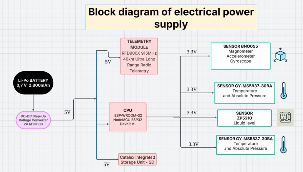
The block diagram illustrates the electrical power supply system of a telemetry and sensor device. The system is powered by a 3.7V 2800mAh Li-Po battery, which is connected to a DC-DC step-up voltage converter (MT3608) that boosts the voltage to 5V. This 5V line is distributed to various components.
The CPU, an ESP-WROOM-32 (NodeMCU ESP32 DevKit V1), receives 5V and internally regulates the voltage to 3.3V using its built-in voltage regulator. The ESP32 then supplies 3.3V to various sensors and peripherals, ensuring proper operation.
The telemetry module, an RFD900X operating at 915MHz, is powered directly by the 5V line to enable long-range communication of up to 40 km. Additionally, a Catalex storage module (SD card) is powered with 5V for data logging.
The system includes several sensors operating at 3.3V:
- BNO055: A 9-degree-of-freedom sensor integrating a magnetometer, accelerometer, and gyroscope.
- Two GY-MS5837-30BA sensors: Used to measure temperature and absolute pressure.
- ZP5210: A sensor designed for liquid level measurement.
This power distribution ensures that each component receives the necessary voltage levels, maintaining system efficiency and reliability.